|
Physics of biology and medicine
Reference:
Konoplev, I.V., Dey, S., Zelenkova, M.N. (2023). Concept of Monobloc, Traveling Wave, Space Charge Current Limited Linear Accelerator for Radiotherapy in Oncology. Physics of biology and medicine, 1, 79–98. . https://doi.org/10.7256/2730-0560.2023.1.39856
Concept of Monobloc, Traveling Wave, Space Charge Current Limited Linear Accelerator for Radiotherapy in Oncology
Konoplev Ivan Vasilevich
Professor of the Department of Physics, Institute of Advanced Studies, Sevastopol State University
33 Universitetskaya str., Sevastopol, 299053, Russia

|
ikonoplev202@gmail.com
|
|
 |
Dei Sparshita
PhD student of the Department of Physics at University of Oxford
OX1 3RH, United Kingdom, Oxford, Keble Road, Denis Wilkinson Building, room 504
|
|
s.dey@physics.ox.ac.uk
|
|
|
|
Zelenkova Marina Nikolaevna
Junior Researcher of the Research Laboratory "Molecular and Cellular Biophysics", Institute of Advanced Studies, Sevastopol State University
33 Universitetskaya str., Sevastopol, 299053, Russia
|
|
marina.zelenkova@gmail.com
|
|
|
|
DOI: 10.7256/2730-0560.2023.1.39856
EDN: SVWBBY
Received:
27-02-2023
Published:
08-06-2023
Abstract:
The number of cancer cases will grow annually and according to WHO it will reach 25 million cases a year by 2035. Radiotherapy (RT) is a key element for the treatment of the 80 % of the cases [1-3] and its development and accessibility are the main routes for further improvement. At the current moment the large percentage of the negative outcomes of the cancer treatment is attributed to either lack of the RT machines or technical personal capable to maintain it. A modular approach to structure such an equipment is one of the ways to resolve the issues. The aim of the studies is to develop a conceptual design of a single module compact accelerator for medical applications and specifically RT of cancers. Development of such a machine is an important step to resolve the RT availability and challenging task from research and design point of view. The studies carried out using analytical and numerical (CST MW studio) approaches. In this paper the conceptual design of such a monobloc traveling wave (12 GHz) accelerator with the space charge limited electron beam current is presented and discussed. The accelerating section made of set of specially designed cell with average constant accelerating potential around 40 MV/m is demonstrated and its properties are discussed. It is shown that the low-relativistic electron beam can reach energy of 10 MeV on the length of the section less than 30 cm. It is shown that the electron beam capture, modulation and transportation takes place inside the accelerating section with the beam transportation efficiency above 80 %. It is illustrated that the main beam losses are taking place at the initial stage of beam formation and ways to optimise the system and minimise the beam losses are discussed. The results of the studies are compared and good agreement is demonstrated.
Keywords:
monobloc linear accelerator, radiotherapy, oncology, compact linear accelerator, traveling wave, space charge, virtual cathode, non-uniform accelerating structure, constant acceleration potential, high-current accelerator
This article is automatically translated.
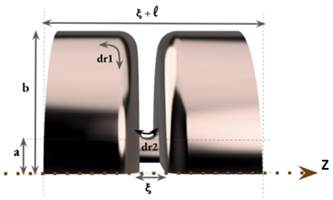
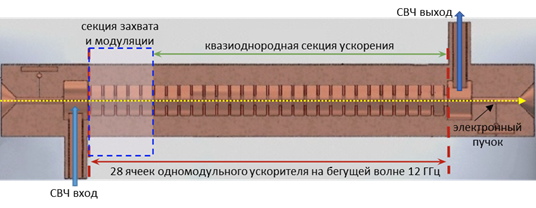
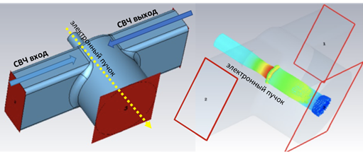
1. Introduction The development and research of compact accelerators, as well as the study of their use in science, medicine and other sectors of the real economy are important and urgent tasks today [1-11]. The development of new accelerators becomes especially important in the light of reports [1-3], which show that within 10-20 years the need for medical accelerators to fight cancer will increase significantly. The initial cost of modern radiotherapy equipment and the cost of maintenance are the main reasons for the shortage and downtime of such equipment not only in emerging economies, but also in developed countries of Europe and America. On the other hand, the development of modern radiotherapy methods, such as FLASH [12-14], poses new challenges for accelerator physics to develop new accelerators with short pulses and high peak and medium currents. Modern accelerators have unique capabilities, but their use is hampered not only by engineering, technical and economic problems, but also by unsolved scientific problems that appear when trying to make accelerators at the same time compact, reliable, easy to operate, cheap to manufacture and maintain. One of the solutions is to create a monoblock accelerator in which the injection, capture, grouping and acceleration of the electron beam occur in one system unit with minimal loss of highly relativistic electrons to reduce the parasitic X-ray radiation affecting the operation of the electronics of the equipment. Together with the permanent magnet system, this solution combines a DC injector, modulating and accelerating sections, as well as a target for producing braking radiation into one module, while reducing the number of power sources and systems that need to be serviced during operation. Such an accelerator will be a ready-made elementary module for operation in a multimodule medical machine for radiotherapy of oncological diseases. In particular, with the use of new permanent Holbach magnets [15-16], it will be possible to reduce the size and mass of the accelerator (up to 40-50 cm, up to 25 kg). "Miniaturization" will allow it to be used to replace the radioactive element Co 60 [17-20] without changing other parts of such a machine. This will also eliminate the risks associated with its subsequent storage and disposal. The development of a new accelerator will reduce the cost and extend the operating time of such machines. The use of a monoblock scheme will allow the use of such accelerators not only in medicine, but also in other sectors of the economy. The article discusses the results obtained during the studies of the accelerating section of a monoblock accelerator on a traveling wave with a current limitation by a spatial charge. It is demonstrated that the capture, modulation and acceleration of the injected weakly relativistic DC beam to operating energies occur in the accelerating section. The stages of calculations of the accelerating structure are shown, the results of these calculations are presented and the main geometric and operating parameters of the system are discussed. In particular, it has been demonstrated that the use of an operating frequency of 12 GHz and a constant accelerating voltage of up to 30 MV/m makes it possible to make the length of the structure consisting of 28 cells less than 30 cm and obtain a beam energy of up to 10 MeV with an average beam output current of up to 0.1 A. Such characteristics will make it possible to use the accelerator not only to replace traditional systems based on the use of radioisotopes and accelerators at longer wavelengths, but also to use it in new cancer treatment regimens [12-14]. The beam current of 0.1 A at a particle energy of up to 10 MeV with a margin provides the dose necessary for radiotherapy of 250 cGy/min [1,2,3,4,5,6,7,8,9,10,11,12,13,14,17,18,19,20]. One of the tasks of the work is to study the production of a relativistic beam with an average current of up to 0.1 A in compact accelerators using an affordable electron beam injector and power sources used in real sectors of the economy. A thermocathode is supposed to be used as an injector, and to obtain the maximum current, the accelerator is proposed to operate in the mode of current limitation by a spatial charge. The initial energy of the injected beam is set to 150 keV, taking into account previous studies of devices operating in the spatial charge limitation mode [21-25], and the requirements for creating an accelerator with an average beam current of up to 0.1 A for wider use in medicine and in the real sector of the economy. At the same time, a power supply of up to 20 kW will be required to power the injector. Lowering the energy of the injected beam will lead to a decrease in the average current at the output of the structure, however, in a number of applications, lower initial voltage and beam current and a smaller power source are possible. Figure 1a shows an elementary cell of the accelerating structure, the designations used later in the article are introduced. The main parameters that have been optimized are the aperture width and the aperture radius a. During the calculations, the cell length and the maximum radius b remained unchanged radius a. During the calculations, the cell length and the maximum radius b remained unchanged . . Figure 1. (a) The cell of the accelerating structure with the geometric parameters shown, which were used to optimize the accelerating structure. (b) Technical drawing of the accelerating structure with inputs and outputs of microwave power. The figure also shows the location of the regular and irregular sections and the beam transport channel. (c) A numerical model of a communication cell (input/output) of microwave power and an illustration of the acceleration of a DC electron beam inside a communication cell. Figure 1b shows a technical drawing of an accelerating structure with input and output microwave power feeders and designated sections with variable and quasi-regular cell geometry. Figure 1b also shows the channels of beam injection and its output to the target. Figure 1b illustrates the first cell of the accelerating structure with power feeders, in which an increase in the beam energy from the initial value of 20 keV to 150 keV was achieved. It should be noted that the illustration shown in Figure 1b is made only for the purpose of demonstrating the acceleration of the beam in one cell in the accelerating potential of the working microwave wave. As is obvious from Figure 1, the initial geometry of the accelerating structure is taken from the CLIC CERN model [10,11,23,26,27,28,29]. The main differences between the CLIC CERN structures and the one considered in this paper arise due to the changed functionality of the new structure in comparison with CLIC CERN. The latter is used as an energy booster of a highly relativistic beam (the structure is powered by a modulated beam with bunch energies above 100 MeV). In this paper, it is assumed that the accelerating structure is powered by a DC beam with an energy of up to 150 keV, an external magnetic field is used to focus the beam and transport it, the average beam current is limited by the spatial charge of the injected beam. Table 1 shows the expected operating parameters: the operating frequency of the traveling wave ~ 12 GHz, the constant gradient of the accelerating voltage, the expected average operating current of 100 mA, the output working energy of the beam up to 10 MeV, the longitudinal structure of the wave (Figure 2a). The choice of values of these parameters is based on the experience of working with CERN CLIC structures, in particular, the use of 12 GHz is dictated by the fact that a further increase in frequency will lead to greater miniaturization of cells and difficulty in transporting high average current. The initial maximum energy of the injected beam of 150 keV (relativistic Lorentz factor (Figure 2a). The choice of values of these parameters is based on the experience of working with CERN CLIC structures, in particular, the use of 12 GHz is dictated by the fact that a further increase in frequency will lead to greater miniaturization of cells and difficulty in transporting high average current. The initial maximum energy of the injected beam of 150 keV (relativistic Lorentz factor ) was chosen as a compromise between increasing the average beam current and using a power source available in the real sector of the economy (up to 20 kW). The working energy of the output beam was limited to 10 MeV to avoid activation of materials with high-energy particles. The accelerating structure operating on a traveling wave was chosen to increase reliability, in particular, in [29-31] it was demonstrated that, unlike accelerators on a standing wave, in structures on a traveling wave, a microwave breakdown is not observed up to accelerating potentials above 100 MV/m. The results presented in the article are obtained as a result of analytical analysis and numerical modeling of the electrodynamic properties of the structure and modeling of beam dynamics. ) was chosen as a compromise between increasing the average beam current and using a power source available in the real sector of the economy (up to 20 kW). The working energy of the output beam was limited to 10 MeV to avoid activation of materials with high-energy particles. The accelerating structure operating on a traveling wave was chosen to increase reliability, in particular, in [29-31] it was demonstrated that, unlike accelerators on a standing wave, in structures on a traveling wave, a microwave breakdown is not observed up to accelerating potentials above 100 MV/m. The results presented in the article are obtained as a result of analytical analysis and numerical modeling of the electrodynamic properties of the structure and modeling of beam dynamics. Table 1. Basic technical operating parameters | Name of the parameter | Parameter value | | Operating frequency f op,GHz | 11,994 | | Structure of the accelerating field | 
| | Type of cells | With a constant gradient of the accelerating field |
| Energy of the injected beam, keV |  150 150
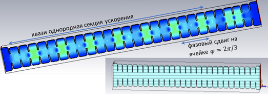
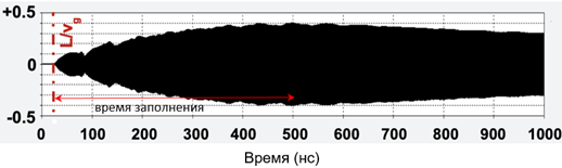
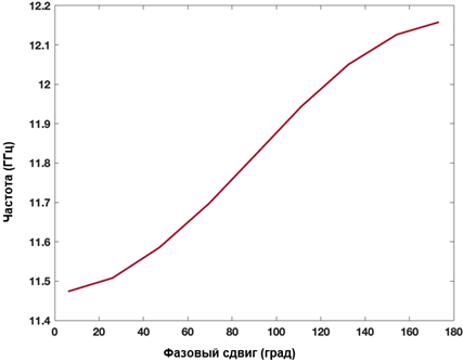
| | Average beam current at the accelerator output, mA | 100 | | Average electron energy at the accelerator output, MeV | 10 | Figure 2. (a) Contour drawing illustrating the distribution of the amplitude of the working accelerating field, the phase shift of the wave along one cell. A regular quasi-homogeneous section of the structure and an adiabatically varying section are visible, which are faintly distinguishable in the technical figure (insert). (b) The evolution of the amplitude of the working field at the exit from the structure. 0 ns corresponds to the injection of a microwave wave into the accelerating structure (the entrance to the first cell), at 40 ns the signal reaches the exit from the last cell. (c) The dependence of the phase shift of the wave along one cell of a regular section on the frequency of the wave. The phase-frequency dependence was studied for each cell of the structure. Table 2 shows the geometric parameters optimized using numerical modeling (3D PiC CST MW Studio software product) to compile a 28-cell accelerating structure (Figure 1a). Table 2. Basic geometric parameters of the accelerating structure, specified and necessary for research and optimization (IiO) | Name of the parameter | Parameter value | | Aperture radius a, mm |
IiO | | Diaphragm length  , mm , mm | IiO | | Radius of cell b, mm | IiO | | Cell length l,keV | 
| | Average beam current at the accelerator output, mA | 100 | | Average electron energy at the accelerator output, MeV | 10 | Section 2 of the article presents the basic equations and the results of the analysis of the structure, geometric and other parameters optimized using numerical modeling are determined. Section 3 of the article presents: the results of numerical modeling and optimization of the structure, the dynamics of the beam is considered, the formation of a virtual cathode is shown, and the results obtained are discussed. In section 4 of the article, the results of numerical simulation are compared with theoretical data and the next steps for designing a compact accelerator are discussed. 2. Basic equations, operating parameters and geometry of the system The accelerating structure is based on a waveguide structure with diaphragms (Figure 1, Figure 2a). The accelerating mode in such a system has a TM mn wave structure (E z working field), which propagates with some attenuation [4,5,10,11,23,26,27,28] The working field of the wave along the structure (along the z coordinate) can be represented as [4,5,10,11,23,26,27,28] The working field of the wave along the structure (along the z coordinate) can be represented as , here m and n describe the number of radial and azimuthal variations of the wave mode. Attenuation occurs due to the presence of thin diaphragms having a supercritical narrowing, with a finite thickness of the diaphragm (Figure 1a). In this problem, the weak attenuation of the wave at the cell length , here m and n describe the number of radial and azimuthal variations of the wave mode. Attenuation occurs due to the presence of thin diaphragms having a supercritical narrowing, with a finite thickness of the diaphragm (Figure 1a). In this problem, the weak attenuation of the wave at the cell length <<1 is considered, that is, the approximation of thin diaphragms <<1 is considered, that is, the approximation of thin diaphragms .It should also be noted that this structure is a resonant system in which 100% wave propagation is observed at natural frequencies. Figure 2b shows the filling of such an inhomogeneous structure with the eigenmode field, and two characteristic times (wave propagation time and filling time) are simply identified. The natural frequencies of such a diaphragm structure are estimated in the approximation of cell uniformity: .It should also be noted that this structure is a resonant system in which 100% wave propagation is observed at natural frequencies. Figure 2b shows the filling of such an inhomogeneous structure with the eigenmode field, and two characteristic times (wave propagation time and filling time) are simply identified. The natural frequencies of such a diaphragm structure are estimated in the approximation of cell uniformity:
 (1) (1)
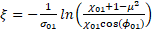
where  n is the root of the Bessel function of the first kind n is the root of the Bessel function of the first kind  and for the fundamental mode (the working mode of the accelerating structure), and for the fundamental mode (the working mode of the accelerating structure),  ; ;  — the phase of the mode on the cell length; b is the radius of the cell; — the phase of the mode on the cell length; b is the radius of the cell; 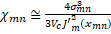 taking into account that the normalized length of the diaphragm taking into account that the normalized length of the diaphragm ; ;  — the volume of the unit cell; — the volume of the unit cell; 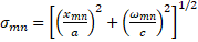 ; a is the radius of the diaphragm. ; a is the radius of the diaphragm. To synchronize the changes, the velocity of the wave phase and the velocity of the electron during its acceleration inside the cell, it is necessary to know the onslaught of the wave phase in the cell. The selection of the lengths and radii of the diaphragms makes it possible to obtain such synchronization, ensuring that the captured electrons of the beam stay only in the accelerating phase of the wave. The change in the phase of the wave at the length of the accelerating cell is defined as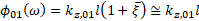 , and its dependence on the frequency of the working wave is shown in Figure 2b. Analyzing the phase , and its dependence on the frequency of the working wave is shown in Figure 2b. Analyzing the phase and group and group velocities: velocities:  (2) (2)
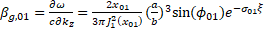 (3) (3)
taking into account that the radius of the cell b = const and the acceleration of electrons is constant, the initial geometric parameters of the cell diaphragm (Figure 1a) are obtained from expressions (2) and (3): 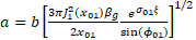 (4) (4)
 (5) (5)
where is the cell parameter that depends only on the radius of the waveguide b. is the cell parameter that depends only on the radius of the waveguide b. Since the phase velocity of the wave must coincide with the velocity of the electron , the geometric parameters of each cell of the accelerating structure can be estimated. In the table 3 the comparison of analytically estimated and numerically optimized cell parameters is given. , the geometric parameters of each cell of the accelerating structure can be estimated. In the table 3 the comparison of analytically estimated and numerically optimized cell parameters is given. Table 3. Changes in the phase velocity of the wave and the length of the cell with a change in the cell number | Cell number | The normalized phase velocity of the wave, |
Cell length, mm | | 1 | 0,758 | 6,32 | | 2 | 0,881 | 7,34 | | 3 | 0,928 | 7,73 | | 4 | 0,951 | 7,93 | | 5 | 0,965 | 8,04 | | 6 | 0,973 | 8,11 | | 7 |
0,979 | 8,16 | | 8 | 0,983 | 8,2 | | 9 | 0,986 | 8,22 | | 10 | 0,988 | 8,24 | | 11 | 0,99 | 8,25 | | 12 | 0,991 | 8,27 | | 13 | 0,993 |
8,28 | | 14 | 0,994 | 8,28 | | 15 | 0,994 | 8,29 | | 16 | 0,995 | 8,29 | | 17 | 0,995 | 8,3 | | 18 | 0,996 | 8,3 | | 19 | 0,996 | 8,3 |
| 20 | 0,996 | 8,31 | | 21 | 0,997 | 8,31 | | 22 | 0,997 | 8,31 | | 23 | 0,997 | 8,32 | | 24 | 0,997 | 8,32 | | 25 | 0,998 | 8,32 | | 26 |
0,998 | 8,32 | | 27 | 0,998 | 8,32 | | 28 | 0,998 | 8,32 | It can be seen from the comparison that the initial estimates already give relatively accurate values of the parameters. In the calculations, it is also necessary to take into account and optimize the group velocity, since the group velocity is directly related to the filling rate of the EM structure by the wave and the efficiency of energy transmission. Figure 2b shows the evolution of the field amplitude at the output of the accelerating structure. The characteristic structure times associated with the signal transmission rate and the "fill" rate are clearly visible in the figure. Due to the difference in cell impedances (the structure in question is inhomogeneous) required for synchronization of a traveling wave and a weakly relativistic electron beam, the time of "filling" the structure with the eigenmode field is relatively long and is 400 ns (determined by the Q-factor of the eigenmode). The signal travel time from the input (the beginning of the structure) to the output (group velocity) is much less and is 40 ns (Figure 2b). Figure 3a shows a comparison of the phase (left axis) and group (right axis) working wave velocities (frequency f =11.994 GHz) and electron velocities (left axis) along the structure. The graphs also show a comparison of the values of the phase velocities of the working wave obtained by analytical and numerical (solid and dotted lines, respectively) methods. The software product CST MW Studio was used for numerical modeling. | 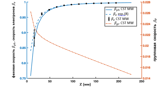
| | but | | 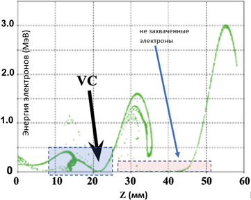
| | b | Figure 3. (a) Dependence of the phase (left axis) and group (right axis) normalized velocities of the working wave depending on the longitudinal coordinate. The normalized electron velocity (left axis) is also given, and a good agreement between the phase velocity of the wave and the longitudinal velocity of the electrons is shown. (b) Electron energy distribution inside the structure when the structure is filled with a beam, the flight time is 0.22 ns.
It can be seen from the graphs that numerical estimates give fairly accurate results, for example, the Q-factor of the working mode calculated using analytical methods (6) is defined as calculated using analytical methods (6) is defined as (in the approximation of uniformity and periodicity of the structure), while numerical modeling of the optimized system gave a value (in the approximation of uniformity and periodicity of the structure), while numerical modeling of the optimized system gave a value  that the discrepancy between numerical and analytical estimates is less than 6 %. that the discrepancy between numerical and analytical estimates is less than 6 %. 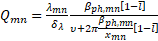 (6) (6)
where  is the depth of the skin layer; is the depth of the skin layer; is the number of cells per wavelength ( is the number of cells per wavelength ( for for  the mode, Figure 2a). the mode, Figure 2a). Note that to increase the average beam current at the output, an electron beam with a constant current and a relatively high electron energy of 150 keV is injected into the accelerating structure. To focus and conduct a weakly relativistic (up to 1 MeV) high-current beam, the structure is placed in a permanent magnetic field. This made it possible to significantly reduce losses on the walls of the structure, especially at the initial stage, when the beam is captured and modulated. The superposition of a magnetic field and a microwave wave leads to the fact that part of the electron beam slows down in the braking phase of the wave, and due to the fields of the spatial charge, a virtual cathode region (VC) is formed [24,25,27,32,33,34]. In the VC region, the electron beam slows down to almost zero energies, . When the beam current exceeds the critical value, some of the electrons will be reflected and lost. The VC remains locked until the appearance of the accelerating field of the microwave wave, which opens the VC, and thus a modulated beam is formed. The higher the charge of the VC, and accordingly the average operating current of the beam, the higher the initial energy of the electrons in the injected beam. A decrease in the initial energy leads to a faster accumulation of charge in the VC, sufficient to reflect the incoming electrons, and a decrease in the average beam current. An increase in the average current is possible either by increasing the accelerating potential of the microwave wave, or by increasing the initial energy of the injected beam. To reduce beam losses at the initial stage, the optimal initial beam current should be slightly less than the critical one, in this case the number of reflected electrons is minimized and the average operating current is maximized. The average beam current of ~100 mA at the output with minimal losses in the initial section of the accelerating structure was obtained at the initial energy of the injected beam of 150 keV. . When the beam current exceeds the critical value, some of the electrons will be reflected and lost. The VC remains locked until the appearance of the accelerating field of the microwave wave, which opens the VC, and thus a modulated beam is formed. The higher the charge of the VC, and accordingly the average operating current of the beam, the higher the initial energy of the electrons in the injected beam. A decrease in the initial energy leads to a faster accumulation of charge in the VC, sufficient to reflect the incoming electrons, and a decrease in the average beam current. An increase in the average current is possible either by increasing the accelerating potential of the microwave wave, or by increasing the initial energy of the injected beam. To reduce beam losses at the initial stage, the optimal initial beam current should be slightly less than the critical one, in this case the number of reflected electrons is minimized and the average operating current is maximized. The average beam current of ~100 mA at the output with minimal losses in the initial section of the accelerating structure was obtained at the initial energy of the injected beam of 150 keV. To capture the beam with an accelerating voltage, we introduce the condition that the electron cannot leave the accelerating potential, and this condition gives us the first estimate of the amplitude of the microwave field. On the other hand, if the accelerating potential is too large, then some of the electrons may be reflected, which will lead to an increase in losses and that determines the second condition for the amplitude of the microwave field. These conditions for successful capture and modulation of the beam determine the critical values of the fields [23,27,28]. 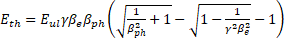 (7) (7)
where and and is the momentum of the electron injected into the accelerating structure normalized by the rest mass. is the momentum of the electron injected into the accelerating structure normalized by the rest mass. Expression (7) allows us to estimate the minimum value of the amplitude of the microwave field in the approximation of the absence of a spatial charge. The value of the field must be adjusted taking into account the spatial charge field where the spatial charge field cannot be neglected, in particular in the region of low beam energies. Figure 4a shows a comparison of the results obtained by numerical (dotted line) modeling and using expression (7) (solid line). | 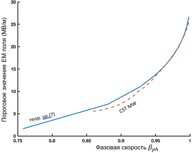
| | but | |
| | b | Figure 4. (a) The dependence of the threshold value of the amplitude of the working field for electron capture on the phase velocity of the wave. Theoretical results (solid line) and numerical simulation results (dotted line) are presented on the graph. (b) The dependence of the capture and retention coefficients (left axis) and the transport coefficient (right axis) on the phase velocity of the wave. The graphs show the dependence of the amplitude of the microwave field on the phase velocity of the wave along the accelerating structure. We assume that an electron is captured by a wave if of the amplitude of the microwave field on the phase velocity of the wave along the accelerating structure. We assume that an electron is captured by a wave if . Thus, taking into account . Thus, taking into account , analyzing expression (7), we obtain , analyzing expression (7), we obtain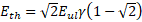 . The second threshold value of the amplitude of the microwave field can be estimated from the condition . The second threshold value of the amplitude of the microwave field can be estimated from the condition (stopping the electron before its reflection), (stopping the electron before its reflection), [27], and if [27], and if , we get , we get . Thus, the minimum value of the amplitude of the microwave field required to capture electrons with different velocities . Thus, the minimum value of the amplitude of the microwave field required to capture electrons with different velocities was estimated at 26.67 MV/m (Figure 4a). Note that to provide such an amplitude of the accelerating microwave field, a ~3 MW microwave source is needed. Beam transportation from the injection point to the target is determined by the capture coefficients: was estimated at 26.67 MV/m (Figure 4a). Note that to provide such an amplitude of the accelerating microwave field, a ~3 MW microwave source is needed. Beam transportation from the injection point to the target is determined by the capture coefficients: 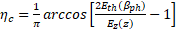 (8) (8)
and deductions: 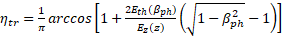 (9) (9)
electrons in the accelerating phase. The beam retention coefficient, which determines the efficiency of transportation, is defined as the ratio of the electrons remaining and brought to the target to the number of captured electrons at the initial stage. It is obvious that in an ideal structure (without beam losses) the efficiency of transportation The beam retention coefficient, which determines the efficiency of transportation, is defined as the ratio of the electrons remaining and brought to the target to the number of captured electrons at the initial stage. It is obvious that in an ideal structure (without beam losses) the efficiency of transportation . . Figure 4b shows graphs of the capture and retention efficiencies (left axis), as well as the transportation efficiency (right axis) depending on the phase velocity of the wave. The graphs are obtained taking into account the electron velocity during beam injection of the wave. The graphs are obtained taking into account the electron velocity during beam injection (beam energy 150 keV), with the acceleration potential of 26.67 MV/m fixed, and using the above expressions for the threshold values of the fields. For these beam parameters and fields, the maximum efficiency (beam energy 150 keV), with the acceleration potential of 26.67 MV/m fixed, and using the above expressions for the threshold values of the fields. For these beam parameters and fields, the maximum efficiency of 0.91 is obtained at a velocity of 0.91 is obtained at a velocity of 0.705, which corresponds to an electron energy of 200 keV ( of 0.705, which corresponds to an electron energy of 200 keV ( ) and is achieved in the first cells of the regular section of the accelerating structure (Figure 1b). The captured and modulated beam is accelerated in the structure, and when beam energies above 1 MeV are reached, the influence of the focusing magnetic field can be neglected. Figure 5 shows graphs of the dependence of the energy of the beam particles (change in the relativistic factor) (left axis) and the efficiency of their transportation (right axis), ) and is achieved in the first cells of the regular section of the accelerating structure (Figure 1b). The captured and modulated beam is accelerated in the structure, and when beam energies above 1 MeV are reached, the influence of the focusing magnetic field can be neglected. Figure 5 shows graphs of the dependence of the energy of the beam particles (change in the relativistic factor) (left axis) and the efficiency of their transportation (right axis), , (the ratio of the number of particles in this section to the number of particles in the previous step) on their position inside the structure. The dependences are considered both with the magnetic field turned on (calculated using 3D PiC CST MW Studio) and without a magnetic field using a system of equations of electron motion: , (the ratio of the number of particles in this section to the number of particles in the previous step) on their position inside the structure. The dependences are considered both with the magnetic field turned on (calculated using 3D PiC CST MW Studio) and without a magnetic field using a system of equations of electron motion: 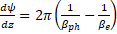 (10a) (10a)
 (10b) (10b)
where is the relativistic Lorentz factor, is the relativistic Lorentz factor, is the phase of the electron relative to the wave, is the phase of the electron relative to the wave, is the normalized amplitude of the microwave field. is the normalized amplitude of the microwave field.
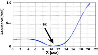
Figure 5. Dependence of the beam transportation efficiency (right axis) on the beam position. The results of theoretical calculations (solid line) and numerical modeling (dots) are presented, their coincidence in the regular section of the accelerator is shown. The results of theoretical calculations (dotted line) and numerical modeling of the dependence of the beam energy on its position in the accelerating structure are presented. As can be seen from Figure 5, the results of evaluating the efficiency of beam transportation obtained by numerical modeling and analysis of equations (8) differ at the initial stage. At the initial segment of the structure, the beam energy is small, and the external magnetic field and the spatial charge fields strongly affect the dynamics of electrons. At beam energies of more than 1 MeV, the influence of both the spatial charge and the leading magnetic field is insignificant, and the results practically repeat each other. These results, in particular, make it possible to limit the length of the magneto-optical system and use, for example, permanent magnets of the Holbach type [15-16], eliminating the need for additional power sources. The dependence of the beam energy on its position inside the structure is also shown. The results obtained by numerical modeling and using equations (10) are compared. The difference between the graphs is explained by the approximate description of the field in the structure in equations (10) and the neglect of the spatial charge fields, which significantly affect the dynamics at the initial stage. Thus, equations (10) give inflated values of the beam energy in each section of the structure. 3. Numerical modeling of the uprooting structure and beam dynamics As shown in the previous section, analytical models allow you to estimate the initial parameters for the design of the system. Nevertheless, as shown in Figure 5, the estimates remain approximate and numerical modeling is necessary to optimize the structure in order to obtain a system with the specified parameters. For numerical modeling in this work, the modules of the 3D CST MW Studio software product are used, which allow calculating the electrodynamic characteristics of the structure, such as the reflection coefficients S 11 and the passage S 12 of the electromagnetic wave, eigenmodes and their Q-factors, as well as the dynamics of particles in external microwave and magnetic fields, taking into account the spatial charge. An illustration of the numerical model of the structure used in the research is shown in Figure 2a, which also shows the distribution of the E z field of the working mode. The geometric parameters of the cells after preliminary optimization are shown in Table 3. Note that when optimizing the structure, the power feeder and power outlet channels (caplers) were not considered. The addition of cells with input and output caplers (Figure 1b) will lead to a slight shift in operating frequencies and an increase in the Q-factor of the operating mode. Figure 6 shows the amplitudes of the reflection coefficients S 11 and transmission S 12, obtained by numerical simulation, in a range close to the operating frequency. 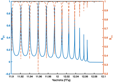
Figure 6. Dependences of transmission coefficients S 12 (left axis) and reflection S 11 (right axis) in the frequency range 11.9–12.1 GHz. The minima/maxima of the functions correspond to the centers of the passage zones. The coefficient of passage of the working mode is ~ 0.92, which is lower than the coefficient of passage (S 12 = 0.97) of the neighboring mode at a frequency of 11.92 GHz. With the addition of additional cells for the input and output of microwave power, it is expected that the optimal value of the transmission coefficient S 11 of the working mode will be achieved. Optimization of the geometric parameters of the structure and development of technical documentation will be carried out after calculating all individual elements and combining them into one system for numerical modeling. At this stage of the work, the initial optimization of the accelerating system was carried out to demonstrate the possibility of using a monoblock structure for capturing, modulating, accelerating and efficiently transporting the beam. Table 4 shows a comparison of the optimized geometric parameters of the cells with the initial estimated parameters obtained by analytical methods. The optimization is carried out for better synchronization of the electron beam and the phase velocity of the wave, as well as to reduce beam losses on the accelerating structure. Table 4 shows that the estimated radius of the cell was overestimated, while the radius of the diaphragm was underestimated. Table 4. C equalization of the optimized geometric parameters of cells with the initial estimated parameters obtained by analytical methods | Cell number | Aperture radius, mm (estimate) | Aperture radius, mm (optimization) | Cell radius, mm (estimate) | Cell radius, mm (optimization) |
| 1 | 3,24 | 3,50 | 10,71 | 10,36 | | 2 | 3,06 | 3,20 | 10,54 | 10,14 | | 3 | 3,0 | 3,17 | 10,49 | 10,10 | | 4 | 2,96 | 3,16 | 10,46 |
10,08 | | 5 | 2,94 | 3,16 | 10,45 | 10,07 | | 6 | 2,92 | 3,14 | 10,44 | 10,06 | | 7 | 2,9 | 3,14 | 10,43 | 10,06 | | 8 | 2,88 | 3,13 |
10,43 | 10,05 | | 9 | 2,87 | 3,12 | 10,43 | 10,05 | | 10 | 2,85 | 3,11 | 10,42 | 10,05 | | 11 | 2,84 | 3,11 | 10,42 | 10,05 | | 12 | 2,82 |
3,10 | 10,42 | 10,04 | | 13 | 2,81 | 3,09 | 10,42 | 10,04 | | 14 | 2,80 | 3,08 | 10,42 | 10,04 | | 15 | 2,78 | 3,08 | 10,42 | 10,03 | | 16 |
2,77 | 3,08 | 10,42 | 10,03 | | 17 | 2,75 | 3,08 | 10,42 | 10,03 | | 18 | 2,74 | 3,07 | 10,42 | 10,03 | | 19 | 2,73 | 3,07 | 10,42 | 10,03 |
| 20 | 2,71 | 3,07 | 10,42 | 10,03 | | 21 | 2,70 | 3,06 | 10,42 | 10,03 | | 22 | 2,68 | 3,06 | 10,42 | 10,03 | | 23 | 2,67 | 3,06 | 10,42 |
10,03 | | 24 | 2,65 | 3,06 | 10,42 | 10,03 | | 25 | 2,64 | 3,06 | 10,42 | 10,03 | | 26 | 2,62 | 3,06 | 10,42 | 10,03 | | 27 | 2,61 | 3,06 |
10,42 | 10,03 | | 28 | 2,60 | 3,05 | 10,42 | 10,03 | Figure 7 shows the results of studies of the dependence of the absolute beam emittance along the accelerating structure on the amplitude of the focusing magnetic field. along the accelerating structure on the amplitude of the focusing magnetic field. | 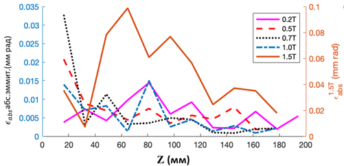
| | but | | 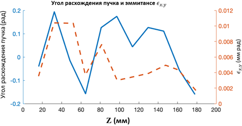
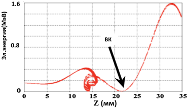
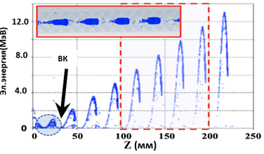
| | b | Figure 7. (a) Dependences of the absolute value of the beam emittance depending on the position of the beam inside the structure, obtained for the values of focusing magnetic fields 0.2 T, 0.5 T, 0.7 T, 1.0 T (left axis) and 1.5 T (right axis). (b) The dependence of the divergence angle (left axis, solid line) and the transverse emittance of the beam on its position in the accelerating structure at the amplitude of the leading magnetic field of 0.7 T. As expected, there are modes of insufficient focusing (B ext<0.5 T) and refocusing (B ext>1.0 T) of the beam with an optimal emittance value achieved at magnetic field values in the range (0.5 T< B ext <1.0 T). Figure 7a highlights a mode with a 1.5 T leading field (the axis on the right). With such a field, the beam emittance is significantly higher than the beam emittance observed at fields up to 1 T. A large emittance value indicates potentially large losses of the electron beam on the walls of the structure, which can lead to parasitic X-ray radiation outside the target area and a drop in the reliability of all equipment. Figure 7b shows the dependences of the angular divergence (left axis) of the beam and its transverse emittance (right axis) with a leading magnetic field of 0.7 T. It can be seen from the graphs that these parameters take the greatest value at the beginning of the structure, where the modulated beam is formed and where the beam energy is below 1 MeV. Figure 8 shows the evolution of the beam as it passes through the accelerating structure. Figure 8. Dependences of the electron energy at time points: (a) 0.09 ns; (b) 0.14 ns; (c) 1.35 ns on the position in the accelerating structure. Each point of the graph represents a charged particle. Graphs (a) and (b) show an accelerator structure partially filled with an electron beam, a transient mode of operation. Graph (b) shows a beam-filled structure, stationary mode of operation. The graphs show the formation of the virtual cathode zone, as well as a certain number of charged particles not captured by the accelerating potential. As discussed above, the capture and modulation of the beam occurs in the initial section (the first 3-4 accelerating cells) of the accelerating structure in the combined fields of the spatial charge, the working microwave mode and the external magnetic field. Figures 8a, b illustrate the dynamics of particles when filling the structure. Figure 8b shows the stationary mode of operation of the system. In particular, the temporal evolution of the virtual cathode is visible, its formation is not in one plane, but in a certain volume. After the VC, electrons are captured in the accelerating phase and accelerated. It can be seen that in the space of the virtual cathode, the dynamics of electrons is complex, in particular, the electron energy drops to almost zero (electrons stop). Figure 8b shows the displacement of the beginning of the acceleration of the modulated beam, the inhomogeneous distribution of energy in electron bunches and low-energy uncaptured electrons with energies significantly lower than the energy of the captured beam. As discussed above, the main losses of the beam electrons (up to 10%) occur at the time of their capture and modulation, i.e. at energies well below 100 keV. A small (less than 1%) loss of uncaptured electrons occurs at a regular site (Figure 8b), while their energy is below 1 MeV. 4. Conclusions The accelerating structure discussed in the article is designed, in particular, for use in X-ray therapy devices to replace either radioactive elements such as Co 60 or obsolete accelerators on a standing wave. For use in medicine, as well as in the real sector of the economy, a single-module concept is proposed, when the accelerating structure is powered by a weakly relativistic DC electron beam, and the geometry of the structure and the parameters of the external and intrinsic fields of the beam provide capture, modulation, acceleration and transportation of electrons to the target, in particular for the generation of braking X-rays when used in radiotherapy of oncological diseases. It is shown that the use of an operating frequency of 12 GHz makes it possible, on the one hand, to miniaturize the accelerator unit, and on the other hand, to provide a high, up to 100 mA, average beam current necessary for generating intense X—rays. The concept of a single-module accelerator is presented and a quasi-periodic, compact (length less than 30 cm), distributed structure for capturing, holding and accelerating a weakly relativistic DC electron beam with an initial energy of up to 150 keV is considered. It is shown that such a structure provides beam acceleration of up to 8 MeV with an average current of up to 100 mA (with an initial energy of the injected beam of 150 keV). The current loss does not exceed 20%. The structure presented in the paper consists of 28 cells in which the beam is captured and modulated (in the first four cells) and its subsequent acceleration (the operating frequency of the structure is 12 GHz and the operating mode). By selecting the geometric parameters of each cell, it was possible to synchronize the phase velocity of the working microwave wave and the velocity of the trapped electrons, which ensured uniform acceleration of the electrons (Figure 5) on a traveling wave along the structure. It is demonstrated that the capture and modulation of the beam occurs in a combination of an external magnetic field, an accelerating mode field and a spatial charge field, in which a virtual cathode zone is formed, where the energy of the injected beam drops to almost zero. It is shown that in order to minimize the beam current losses, a part of the accelerating structure, where the beam accelerates from the injection energy to <2 MeV, must be placed in a uniform magnetic field. It is discussed that a focusing, leading magnetic field is necessary only at the initial stage of beam formation (at the length of the first 4-5 cells), which opens up the possibility of using permanent magnets of the Holbach type. The influence of an external magnetic field on the beam emittance was also studied, and it was shown that the optimal values of the fields lie in the range from 0.5 T to 1 T. The use of the operating mode at a relatively high frequency and the traveling wave mode allows, on the one hand, to increase the accelerating gradient to 40 MV/m, and on the other hand, to avoid microwave breakdowns, which are not detected in these systems at voltages greater than 100 MV/m. The margin of "safety" for microwave breakdowns opens up the possibility of manufacturing such structures by grinding (as shown in Figure 9) without additional surface treatment or using additive 3D printing, which will reduce the cost of manufacturing.
Figure 9. Photo of an accelerating structure made of two blocks of copper. The blocks are connected into a vacuum bag by compression using an indium wire. The main advantage of this system is the ability to create an accelerator in which a thermocathode, an accelerating structure, a system of permanent magnets and a target are combined into a single vacuum unit. This will allow you to connect a minimum number of subsystems to such an accelerator. This unit can be changed if necessary and maintained by technical personnel without special access to work with radioactive materials. This work represents the first step in the study and development of a compact monoblock accelerator that combines all elements in a single vacuum package. Further research steps will be the creation of a complete numerical model, the design and construction of a prototype of a monoblock accelerator.
References
1. Zubizarreta, E., & Van Dyk, J., & Lievens, Y. (2017). Analysis of global radiotherapy needs and costs by geographic region and income level. Clinical Oncology, 29(2), 84–92. doi:10.1016/j.clon.2016.11.011
2. Pistenmaa, D., & Dosanjh, M., & Amaldi, U., & Jaray, D., & Zubizarreta, E., & Holt, K., & Lievens, Y., & Pipman, J., & Coleman, C. (2018). Changing the global radiation therapy paradigm. Radiotherapy and Oncology, 128(3), 393–399. doi: 10.1016/j.radonc.2018.05.025
3. Dosanjh, M., & Aggarwal, A., & Pistenmaa, D., & Amankwaa-Frempong, E., & Angal-Kalinin, D., & Boogert, S., … Coleman C. (2019). Developing innovative, robust and affordable medical linear accelerators for challenging environments. Clinical Oncology, 31(6), 352–355. doi:10.1016/j.clon.2019.02.002
4. Hanna, S. (2012). RF linear accelerators for medical and industrial applications. Boston/London: Artech House.
5. Mishin, A. (2005). Advances in X-Band and S-Band Linear Accelerators for Security, NDT, and Other Applications. Proceedings of the 2005 Particle Accelerator Conference, 240–244. doi:10.1109/PAC.2005.1590405
6. Konoplev, I., & Seryi, A., & Lancaster, A., & Metodiev, K., & Burt, G., & Ainsworth, R. (2017). Compact, energy efficient superconducting asymmetric ERL for ultra-high fuxes of x-ray and THz. AIP Conference Proceedings, 1812, 100004. doi:10.1063/1.4975902
7. Konoplev, I. V., & Metodiev, K., & Lancaster, A.J., & Burt, G., & Ainsworth, R., & Seryi, A. (2017). Experimental studies of 7-cell dual axis asymmetric cavity for energy recovery linac. Physical Review Accelerators and Beams, 20, 103501. doi:10.1103/PhysRevAccelBeams.20.103501
8. Tantawi, S., & Nasr, M., & Li, Z., & Limborg, C., & Borchard, P. (2020). Design and demonstration of a distributed-coupling linear accelerator structure. Physical Review Accelerators and Beams, 23, 092001. doi:10.1103/PhysRevAccelBeams.23.092001
9. Kulkarni, N., & Dhingra, R., & Kumar, V. (2016). Physics design of a 10 MeV, 6 kW travelling wave electron linac for industrial applications. Pramana, 87, 74. doi:10.1007/s12043-016-1279-6
10. Aicheler, M., & Burrows, P., & Draper, M., & Garvey, T., & Lebrun, P., & Peach, K., … Toge, N. (2012). A Multi-TeV Linear Collider Based on CLIC Technology: CLIC Conceptual Design Report. Geneva: CERN. doi:10.5170/CERN-2012-007
11. Hajari, Sh. S., & Shaker, H., & Doebert, S. (2015). Beam dynamics design of the Compact Linear Collider Drive Beam injector. Nuclear Instruments and Methods in Physics Research A, 799, 172–186. doi:10.1016/j.nima.2015.07.043
12. Lin, B., & Gao, F., & Yang, Y., &Wu, D., & Zhang, Y., & Feng, G., … Du, X. (2021). FLASH Radiotherapy: History and Future. Frontiers in Oncology, 11, 644400. doi:10.3389/fonc.2021.644400
13. Lin, B., & Huang, D., & Gao, F., & Yang, Y., & Wu, D., & Zhang, Y., … Du, X. (2022). Mechanisms of FLASH effect. Frontiers in Oncology, 12, 995612. doi:10.3389/fonc.2022.995612
14. Borghini, A., & Vecoli, C., & Labate, L., & Panetta, D., & Andreassi, M.G., & Gizzi, L.A. (2022). FLASH ultra-high dose rates in radiotherapy: preclinical and radiobiological evidence. International Journal of Radiation Biology, 98, 127–135. doi:10.1080/09553002.2022.2009143
15. Halbach, K. (1980). Design of permanent multipole magnets with oriented rare earth cobalt material. Nuclear Instruments and Methods, 169(1), 1–10. doi:10.1016/0029-554X(80)90094-4
16. Brooks, S. (2017). Production of low cost, high field quality Halbach magnets. Proceedings of IPAC2017, 4118–4120. Retrieved from https://inspirehep.net/literature/1627381
17. Healy, B. J., van der Merwe, D., Christaki, K. E., & Meghzifene, A. (2017). Cobalt-60 Machines and Medical Linear Accelerators: Competing Technologies for External Beam Radiotherapy. Clinical Oncology, 29(2), 110–115. doi:10.1016/j.clon.2016.11.002
18. Page, B. R., & Hudson, A. D., & Brown, D. W., & Shulman, A. C., & Abdel-Wahab, M., & Fisher, B. J., & Patel, S. (2014). Cobalt, linac, or other: what is the best solution for radiation therapy in developing countries? International Journal of Radiation Oncology Biology, Physics, 89(3), 476–480. doi:10.1016/j.ijrobp.2013.12.022
19. Ramamoorthy, R. (2017). Radioactive Cobalt-60 Teletherapy Machine – Estimates of Personnel Dose in Mock Emergency in Patient Release during “Source Stuck Situation”. Journal of Medical Physics, 42(2), 96–98. doi:10.4103/jmp.JMP_128_16
20. Van Dyk, J., & Battista, J. J. (1995). Cobalt-60: An Old Modality, A Renewed Challenge. Current Oncology, 3. Retrieved from https://www.researchgate.net/publication/238082452_Cobalt60_An_Old_Modality_A_Renewed_Challenge
21. Rokhlenko, A., & Lebowitz, J. L. (2003). Space-Charge-Limited 2D Electron Flow between Two Flat Electrodes in a Strong Magnetic Field. Physical Review Letters, 91, 085002. doi:10.1103/PhysRevLett.91.085002
22. Sree Harsha, N. R., & Halpern, J. M., & Darr, A., & Garner, A. L. (2022). Space-charge-limited current density for nonplanar diodes with monoenergetic emission using Lie-point symmetries. Physical Review E, 106, L063201. doi:10.1103/PhysRevE.106.L063201
23. Wangler, T. (2008). RF Linear Accelerators. Weinheim: Wiley-VCH.
24. Wang, J., & Chen, J., & Cai, L., & Chen, Z., & Ren Z. (2021). Space charge limited current with distributed velocity of initial electrons in planar diode. Physics of Plasmas, 28, 040702. doi:10.1063/5.0044346
25. Nikiforov, D. A., & Petrenko, A. V., & Sinitsky, S. L., & Bak, P. A., & Skovorodin, D. I., & Logachev, P. V., … Akhmetov, A. R. (2021). Investigation of high current electron beam dynamics in linear induction accelerator for creation of a high-power THz radiation source. Journal of Instrumentation, 16, P11024. doi:10.1088/1748-0221/16/11/P11024
26. Argyropoulos, T., & Catalan-Lasheras, N., & Grudiev, A., & Mcmonagle, G., & Rodriguez-Castro, E., & Syrachev, I., … Zha, H. (2018). Design, fabrication, and high-gradient testing of an X-band, traveling-wave accelerating structure milled from copper halves. Physical Review Accelerators and Beams, 21, 061001. doi:10.1103/PhysRevAccelBeams.21.061001
27. Dome, G. (1960). Electron Bunching by Uniform Sections of Disk Loaded Waveguide. Part A: General Study. Stanford: W.W. Hansen Laboratories of Physics.
28. Sullivan, M., & Jones, R. M., & Cowie, L. S., & Brynes, A. D., & Williams, P. H., & Yokoya, K. (2021). X-band linac design. Physical Review Accelerators and Beams, 24, 082001. doi:10.1103/PhysRevAccelBeams.24.082001
29. Dolgashev, V. A., & Faillace, L., & Spataro, B., & Tantawi, S., & Bonifazi, R. (2021). High-gradient RF tests of welded X-band accelerating cavities. Physical Review Accelerators and Beams, 24, 081002. doi:10.1103/PhysRevAccelBeams.24.081002
30. Simakov, E. I., & Dolgashev, V. A., & Tantawi, S. G. (2018). Advances in high-gradient normal conducting accelerator structures. Nuclear Instruments and Methods Physics Research Section A: Accelerators, Spectrometers, Detectors and Associated Equipment, 907, 221–230. doi:10.1016/j.nima.2018.02.085
31. Dolgashev, V., Faillace, L., Spataro, B., & Bonifazi, R. (2018). Innovative compact braze-free accelerating cavity. Journal of Instrumentation, 13, P09017. doi:10.1088/1748-0221/13/09/P09017
32. Fazio, M. V., Kinross-Wright, J., Haynes, B., & Hoeberling, R. F. (1989). The virtual cathode microwave amplifier experiment. Journal of Applied Physics, 66, 2675–2677. doi:10.1063/1.344236
33. Mahaffey, R. A., Sprangle, P., Golden, J., & Kapetanakos, C. A. (1977). High-Power Microwaves from a Nonisochronic Reflecting Electron System. Physical Review Letters, 39, 843–846. doi:10.1103/PhysRevLett.39.843
34. Jiang, W., & Kristiansen, M. (2001). Theory of the virtual cathode oscillator. Physics of Plasmas, 8, 3781–3787. doi: 10.1063/1.1382643
|